Finite-state machine for embedded systems
Get help for finite-state machine programming for embedded systems using C programming language.
Learning Objectives
- Examine a basic implementation of finite-state machine (FSM).
- Look at an improved implementation of FSM.
- See compiled code and supporting diagram and tables for FSM.
One definition of a finite-state machine (FSM) is that FSM is a mathematical model of a sequence of events and actions describing a certain (logical) process. In the engineering practice you can find countless such processes, starting with a very simple process of controlling an electric motor by a couple of push buttons, and ending with a very complex FSM system monitoring a very complicated manufacturing process or a space shuttle.
I once designed firmware for an erbium-dopped fiber-optics amplifier (EDFA) widely used in the optical communication. One firmware segment had to deal with the safety issues of EDFA, which can use powerful lasers harmful to humans if not designed properly. What seemed to be a routine FSM code design, ended with a very complex, difficult to follow and maintain, long procedure. A different way to implement the FSM implementation was needed, which may be of interest to embedded code designers.
Theory of FSM
From the theory of finite automata you might remember two types of FSM representation, a Mealy and Moore finite-state machine. Both types of FSM work upon three sets of variables, a set of input variables, X(k), a set of internal states, U(k) and a set of output variables, Y(k). Both types of FSM use the same transition function, δ, for the mapping U x X → U. The difference between Mealy and Moore FSM is in the second mapping function used for the output states. Mealy’s output states mapping function, λ, represents U x X → Y mapping, while Moore’s λ represents a simpler mapping, just U → Y. From the implementation point of view, while Moore FSM might be simpler, Mealy FSM has certain advantages. For example, it can have more or different output states than the number of the internal states, while in Moore FSM each internal state is associated with one output state.
A generic Mealy FSM can be represented by a following table:

where uk column represents the present internal states, and xk row represents the present input states. And tables show the next internal states (δ mapping) and the corresponding output states (λ mapping).
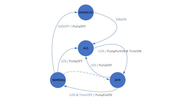
Figure 1 shows another, a more common representation of FSM, the state diagram. What you can see there is a complete state diagram of a one-stage EDFA safety sequence.

Figure 1: One-stage EDFA safety state diagram. Courtesy: Peter Galan, a retired control software engineer
Each EDFA uses one or two (for a more common, two-stage EDFA) laser pumps, which provide the energy to a coil of a special optical fiber placed inside EDFA. This energy amplifies optical signal (photons) flowing through the amplifier from the previous node to the following node. The problems can occur whenever the optical fibers connecting EDFA with other nodes are broken and a loss of signal (LOS) is detected. Such a situation has to be immediately processed, and the laser power has to be reduced or completely shut down. Other conditions also require immediate attention. The entire safety sequence is implemented as one segment of the EDFA firmware.
Basic implementation of FSM
What would be the best programming language for such a finite-state machine (and generally for the embedded control software) implementation? Yes, the C language. There are many other, more modern, object-oriented programming languages, but C is like the “mother language” for the embedded systems. How might an experienced, embedded software designer start to implement this FSM in C? It’s likely to begin with a function like this:

If you look at the code above, you can see how the conditions (event flags combination), if fulfilled, cause a move/change the currState variable from the initial, DISABLED, to the next and the next state. With every such internal state change a specific action – output state is being triggered, in some cases, more than one action.
So far so good, but as the entire process becomes more complex, the if – else decision-making statements become more complex (and deeper nested) as well. Then, if there is a need to modify any of the if – else decision-making statement, it might affect many remaining statements. Next, the entire processing function will require testing again and again. A two-stage EDFA will require two such (similar, though not identical) FSM functions plus another FSM function governing the ADFA amplifier, which will take a lot of effort.
Improved implementation of FSM
There is another way of the finite-state machine representation. It is via a state transition table (STT). STT is another form of the Mealy FSM description. Such a table often has four columns and as many rows as needed. Each row describes a transition from the Present State to the Next State. The transition is triggered by the Event (a combination of one or more event flags). The Action describes all the actions associated with the transition. This is, for example, an STT (just its fragment) corresponding to the state diagram shown in the figure.

Why is such a representation better than a state diagram? Because it can be implemented much more elegantly. Below, see how it can be implemented in the C language.
An experienced software designer would split FSM code into several source files, and begin with the FSM_example.h header file, which will contain the special type definitions and all the function prototypes. A good example of such a header file follows.

The first two definitions might be worth explanation for any less experienced programmers. Each defines a name of a specific function pointer. In C#, those definitions are equal to the definitions using the delegate keyword. They are very powerful tools in C programming, allowing C programs to be written as elegantly as if they used an object-oriented programming language like C#.
Here is the second source file, where all, previously defined function prototypes are fully implemented.


All except the last function should be pretty clear. One type are functions of the F_FSM_EVENT_T type, and they test certain system states (flags) and returning either a true or false value. Notice the “paired” functions like IsLosON() and IsLosOFF(). Only one of them really tests, in this particular case, a loss of the input signal via a hardware (H/W) reported status/flag. If the loss of signal has been detected, this function returns true otherwise it returns false. And the second function is just kind of a wrapper, which calls the first function and returns a negated result.
The second type of functions defined here are of the F_FSM_ACTION_T type. Those functions are the “action” functions, they control (turn on or off) a desired internal/external device of the micro-controller or some H/W circuits, which the entire embedded system consists of.
Both types of functions are needed regardless how the FSM is being implemented, such as a “state diagram” procedure, or the STT implementation. Now, the FSM_sstKernel() function is something new. It replaces the “state diagram” implementing function, FSM_stage1(). And it works upon a STT-type data. Those data are defined as of the S_FSM_STT_T type, and they are provided as an argument to the FSM_sstKernel() function. They have to be provided as a reference/pointer to the S_FSM_STT_T type data as FSM_sstKernel() will be modifying at least one data item.
What FSM_sstKernel() is doing is very simple. It is “looping” through the rows (array elements) of the S_FSM_ROW_T type, and looking for the row with presentState being same as the current internal state, currentState. If such a row found, its event testing functions are called and their returned values are “and-ed” together to find out if the condition for moving to the next internal state is fulfilled. There’s a limit of 2 logical values “and-ed” together. If more are needed, extend the S_FSM_ROW_T data structure by another F_FSM_EVENT_T-type event. What about conditions/events, which have to be “or-ed” together for such transitions between internal states? Each event (or they “and-ed” combination) will have to be provided in a separate, but otherwise identical row.
FSM_sstKernel() then continues (if the transient condition is fulfilled) with launching all the actions found in the row data. Finally it copies the row’s nextState to the stt’s currentState.
What if I want to use FSM_sstKernel() for more FSMs with a diametrically different number of STT rows? The ROW_MAX constant will have to be defined to satisfy the longest STT, but the best solution would be to replace the array of rows with a linked list of rows. Then each S_FSM_STT_T-type data will use an optimal memory space. However, some simple embedded systems won’t allow use of dynamically allocated memory space.
Now, by uncommenting those two printf() statements in FSM_sstKernel(), can see how FSM progresses from the current/present state farther to the next state. This apparently will not work in an embedded system, but entire code may be tested on PC, in Microsoft Visual Studio, for example.
Completing and compiling
Once the FSM_example.h and FSM_example.c are completed (you can even compile them and create their .obj file) you can add them to your application. In another source file the STT table will need to be created. It means to define, at first each row of STT, and finally the STT itself. Then you can call the FSM_sstKernel() function. Very likely you will call it as one of the background tasks in the main() function of your F/W application. And you can define more such S_FSM_STT_T variables and call FSM_sstKernel() with reference to each of them.
For a better visualization write the following source file on PC under MS Visual Studio:

Courtesy: Peter Galan, a retired control software engineer
When you compile and run the program (together with FSM_example.h and FSM_example.cpp) with those two printf() statements inside FSM_sstKernel() uncommented, you should see a result as shown in the following screen shot:

One stage EDFA safety state diagram simulation. Courtesy: Peter Galan, a retired control software engineer
Peter Galan is a retired control software engineer. Edited by Mark T. Hoske, content manager, Control Engineering, CFE Media and Technology, mhoske@cfemedia.com.
MORE ANSWERS
KEYWORDS: Finite-state machine, FSM, embedded system programming
CONSIDER THIS
If your control systems rely on decades-old control methods, are you getting decades-old results?
Do you have experience and expertise with the topics mentioned in this content? You should consider contributing to our CFE Media editorial team and getting the recognition you and your company deserve. Click here to start this process.
